EP0510384A1 - Shoe/boot system with a speedily changeable sole element - Google Patents
Shoe/boot system with a speedily changeable sole element Download PDFInfo
- Publication number
- EP0510384A1 EP0510384A1 EP92105431A EP92105431A EP0510384A1 EP 0510384 A1 EP0510384 A1 EP 0510384A1 EP 92105431 A EP92105431 A EP 92105431A EP 92105431 A EP92105431 A EP 92105431A EP 0510384 A1 EP0510384 A1 EP 0510384A1
- Authority
- EP
- European Patent Office
- Prior art keywords
- shoe
- boot system
- sole
- reciprocal
- clamping assembly
- Prior art date
- Legal status (The legal status is an assumption and is not a legal conclusion. Google has not performed a legal analysis and makes no representation as to the accuracy of the status listed.)
- Granted
Links
Images

Classifications
-
- A—HUMAN NECESSITIES
- A43—FOOTWEAR
- A43B—CHARACTERISTIC FEATURES OF FOOTWEAR; PARTS OF FOOTWEAR
- A43B3/00—Footwear characterised by the shape or the use
- A43B3/24—Collapsible or convertible
-
- A—HUMAN NECESSITIES
- A43—FOOTWEAR
- A43B—CHARACTERISTIC FEATURES OF FOOTWEAR; PARTS OF FOOTWEAR
- A43B13/00—Soles; Sole-and-heel integral units
- A43B13/28—Soles; Sole-and-heel integral units characterised by their attachment, also attachment of combined soles and heels
- A43B13/36—Easily-exchangeable soles
-
- A—HUMAN NECESSITIES
- A43—FOOTWEAR
- A43B—CHARACTERISTIC FEATURES OF FOOTWEAR; PARTS OF FOOTWEAR
- A43B5/00—Footwear for sporting purposes
- A43B5/04—Ski or like boots
- A43B5/0415—Accessories
- A43B5/0417—Accessories for soles or associated with soles of ski boots; for ski bindings
-
- A—HUMAN NECESSITIES
- A43—FOOTWEAR
- A43B—CHARACTERISTIC FEATURES OF FOOTWEAR; PARTS OF FOOTWEAR
- A43B5/00—Footwear for sporting purposes
- A43B5/16—Skating boots
Definitions
- This invention concerns a shoe/boot system with a speedily changeable sole element according to the main claim.
- the invention concerns a shoe/boot system, advantageously with a skiing-type extractable inner slipper, together with a sole element which can be replaced with soles formed for special uses.
- the shoe/boot systems of the type of this invention are shoes/boots with a substantially rigid lower element and with an inner slipper which advantageously can be extracted.
- Shoe/boot systems which have an extractable inner slipper and of which the sole element can be changed are known.
- a shoe/boot system made of a thermal resistant material and including an extractable inner slipper and a changeable sole element is known. It comprises two sole elements, one of which is equipped with a skate for skating on ice, whereas the other has a plurality of rollers for practising on roads so as to simulate ice skating.
- the structure of the sole element is expressly designed for the function it has to perform and does not allow the application of different equipment.
- the base element of the shoe or boot comprises on its lower side lengthwise guides, which cooperate with mating means included on the upper side of the sole to be changed.
- the reciprocal guide means serve at least for the correct lengthwise and lateral positioning of the shoe/boot and changeable sole in relation to each other.
- a quick-release reciprocal clamping and unclamping assembly is included in cooperation with the guide means.
- This reciprocal clamping assembly includes a quick actuation means such as a push button, a lever or a threaded element which acts on at least one retaining and/or positioning element.
- the retaining and/or positioning element creates a reciprocal locking together of the shoe and sole, and this locking can be obtained in a vertical or horizontal direction.
- shoe/boot system is referenced generically with the number 10.
- the lower part of the system is referenced with 11 and in this case comprises a lengthwise positioning and guide element 12 including a frontal retaining prong 13.
- Guide means 14 are firmly secured to, and cooperate with the lengthwise element 12 and are two in number in this example, namely front guide means 14a and rear guide means 14b respectively, and in turn comprise lateral male guide means 15a and lateral female guide means 15b.
- the rear guide means 14b include a reciprocal clamping assembly 16 with positioning and anchorage teeth 17 acting on a horizontal plane.
- the reciprocal clamping assembly 16 can be actuated quickly from the rear, as we shall see later.
- a changeable sole is referenced generically with 20 and comprises in this case lateral elements 18 which include mating guide means 114 with lateral guides 19, which are a male guide 19a and female guide 19b respectively.
- the mating guide means 114 with their relative lateral guides 19 mate with the guide means 14 and lateral guides 15 of the shoe/boot system 10.
- the changeable sole 20 includes at its front a space 21 which contains and positions the frontal prong 13 of the shoe/boot system 10, thus creating a rigid reciprocal joint.
- the changeable sole 20 comprises in congruent cooperation with the positioning and anchorage teeth 17 of the shoe/boot system 10 a seating 22 to receive the relative positioning and anchorage tooth 17.
- the changeable sole 20 is inserted or withdrawn lengthwise at the front of the shoe/boot system 10, and the device to cause its connection or release is located at the rear in a protected zone.
- the changeable sole 20 can be embodied with various forms. Thus there can be skiing soles (Fig.2a), ice skating soles (Fig.2b), roller skating soles for training purposes (Fig.2c), soles with tracks for training purposes (Fig.2d), soles with slides for use on roads (not shown here), soles for walking with their lower part made of rubber (Fig.2e), etc; the soles 20 remain the same, and only their lower special form is varied and meets with a broad area of connection, readily made suitable for the specific purposes and for the specific technical and functional requirements.
- Figs.4 and 5 show two possible reciprocal clamping assemblies 16.
- a push button 23 is solidly secured to a frontal body 24 that contains two inclined slots 25; the push button 23 is resisted resiliently by a spring 27.
- Pins 26 cooperate with the slots 25 and are integrally fixed to sliders which comprise at their ends the positioning and anchorage teeth 17.
- the frontal conformation of the positioning and anchorage teeth 17 enables the sole 20 to be inserted simply by being thrust, or else by thrusting the shoe/boot system 10 within the sole 20.
- the reciprocal clamping assembly 16 contains means 28 for the insertion of fixture screws into the lengthwise positioning and guide element 12, which includes an appropriate seating. This enables corrective action to be taken on the reciprocal clamping assembly 16 speedily and easily whenever maintenance is required.
- the reciprocal clamping assembly 16 is shown diagrammatically and has an analogous function, but the positioning and anchorage teeth 17 consist of a resilient material.
- the positioning and anchorage teeth 17 can have different conformations, such as that shown in Fig.6 for instance.
- the sole 20 includes at its front end a bevel 31 for independent insertion.
- the positioning and anchorage teeth 17, whatever their conformation may be, can act not only at the sides but also vertically at the bottom of the shoe/boot system 10.
- teeth 17 there may be one or more teeth 17.
- reciprocal clamping assembly 16 can be positioned in the sole 20 instead of the shoe/boot system 10.
- the reciprocal clamping assembly 16 may comprise a crank, a lever or a handle which works, for instance, on a threaded shaft with a circular cam element having an axial tapered extent, or else on a shaft conformed peripherally with a cam so as to position the means which disactuate the positioning and anchorage teeth 17.
- the lower part 11 of the shoe/boot system 10 comprises a positive or negative peripheral impression, with which there cooperates peripherally a plurality of positioning and anchorage teeth 17.
- This impression covers the lower part 11 of the shoe/boot system 10 substantially along the whole periphery apart from the space necessary for actuation of the reciprocal clamping assembly 16.
- These positioning and anchorage teeth 17 comprise a self-actuation lead-in for insertion in the lower part of the shoe/boot system 10.
- the sole 20 includes an impression which mates with the impression in the shoe/boot system 10 and is inverted in relation thereto so that one impression is tightly contained in the other.
- the positioning and anchorage teeth 17, when the two impressions have been positioned reciprocally, are anchored in appropriate peripheral seatings 22, thus joining firmly together the sole 20 and the shoe/boot system 10.
- the reciprocal clamping assembly 16 then takes action to disactuate the positioning and anchorage teeth 17, thus enabling the sole 20 to be separated from the shoe/boot system 10.
Abstract
Description
- This invention concerns a shoe/boot system with a speedily changeable sole element according to the main claim.
- To be more exact, the invention concerns a shoe/boot system, advantageously with a skiing-type extractable inner slipper, together with a sole element which can be replaced with soles formed for special uses.
- The shoe/boot systems of the type of this invention are shoes/boots with a substantially rigid lower element and with an inner slipper which advantageously can be extracted.
- Shoe/boot systems which have an extractable inner slipper and of which the sole element can be changed are known.
- A shoe/boot system made of a thermal resistant material and including an extractable inner slipper and a changeable sole element is known. It comprises two sole elements, one of which is equipped with a skate for skating on ice, whereas the other has a plurality of rollers for practising on roads so as to simulate ice skating.
- This known boot entails the drawback that the sole elements with their two special forms are connected to the boot with screws.
- This involves many shortcomings such as long replacement times; the need of tools to screw up and unscrew the screws; the risks of jamming the screws owing to the infiltration of water and/or ice; the risk of excessive pressure of the head of the screw with resulting breakages or small cracks in one or another of the plastic parts; the need to remove the shoe or boot from the foot so as to make the change, etc.
- Moreover, the structure of the sole element is expressly designed for the function it has to perform and does not allow the application of different equipment.
- To obviate these shortcomings and to be able to widen the uses of the shoe/boot system in question, the present applicant has designed, tested and embodied this invention.
- The shoe/boot system with an extractable inner slipper and with a speedily changeable sole element according to the invention is set forth and characterized in the main claim, while the dependent claims describe variants of the idea of the embodiment.
- According to the invention the base element of the shoe or boot comprises on its lower side lengthwise guides, which cooperate with mating means included on the upper side of the sole to be changed.
- The reciprocal guide means serve at least for the correct lengthwise and lateral positioning of the shoe/boot and changeable sole in relation to each other.
- These guide means, as regards their conformation, have the purpose also of providing a constraint operating on a plurality of axes.
- According to the invention a quick-release reciprocal clamping and unclamping assembly is included in cooperation with the guide means.
- This reciprocal clamping assembly includes a quick actuation means such as a push button, a lever or a threaded element which acts on at least one retaining and/or positioning element.
- The retaining and/or positioning element creates a reciprocal locking together of the shoe and sole, and this locking can be obtained in a vertical or horizontal direction.
- Let us now see a preferred embodiment of the invention with the help of the attached figures, of which:-
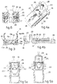
- Fig.1
- is a side view of the lower part of a shoe/boot system according to the invention;
- Figs.2a to 2e
- show lengthwise sections of some specially formed changeable soles able to cooperate with the shoe/boot system of Fig.1;
- Fig.3
- shows a cross section of a connection made with lengthwise guide means between a sole and a shoe/boot system;
- Figs.4a and 4b
- show a possible reciprocal speedy clamping and unclamping assembly;
- Figs.5a and 5b
- shows a further possible reciprocal speedy clamping and unclamping assembly;
- Fig.6
- shows a variant of the assemblies of Figs.4 and 5.
- In the figures a shoe/boot system is referenced generically with the
number 10. - The lower part of the system is referenced with 11 and in this case comprises a lengthwise positioning and
guide element 12 including a frontal retainingprong 13. - Guide means 14 are firmly secured to, and cooperate with the
lengthwise element 12 and are two in number in this example, namely front guide means 14a and rear guide means 14b respectively, and in turn comprise lateral male guide means 15a and lateral female guide means 15b. - In this example the rear guide means 14b include a
reciprocal clamping assembly 16 with positioning andanchorage teeth 17 acting on a horizontal plane. - The
reciprocal clamping assembly 16 can be actuated quickly from the rear, as we shall see later. - A changeable sole is referenced generically with 20 and comprises in this case
lateral elements 18 which include mating guide means 114 withlateral guides 19, which are amale guide 19a andfemale guide 19b respectively. - The mating guide means 114 with their relative
lateral guides 19 mate with the guide means 14 and lateral guides 15 of the shoe/boot system 10. - In this example the
changeable sole 20 includes at its front aspace 21 which contains and positions thefrontal prong 13 of the shoe/boot system 10, thus creating a rigid reciprocal joint. - The changeable sole 20 comprises in congruent cooperation with the positioning and
anchorage teeth 17 of the shoe/boot system 10 aseating 22 to receive the relative positioning andanchorage tooth 17. - In the example shown the
changeable sole 20 is inserted or withdrawn lengthwise at the front of the shoe/boot system 10, and the device to cause its connection or release is located at the rear in a protected zone. - The changeable sole 20 can be embodied with various forms. Thus there can be skiing soles (Fig.2a), ice skating soles (Fig.2b), roller skating soles for training purposes (Fig.2c), soles with tracks for training purposes (Fig.2d), soles with slides for use on roads (not shown here), soles for walking with their lower part made of rubber (Fig.2e), etc; the
soles 20 remain the same, and only their lower special form is varied and meets with a broad area of connection, readily made suitable for the specific purposes and for the specific technical and functional requirements. - Other special forms of the sole 20 can therefore be provided, so that a user can readily equip himself according to his momentary personal requirements owing to the speed and great ease of assembling or dismantling the system thus existing.
- Figs.4 and 5 show two possible
reciprocal clamping assemblies 16. - According to Fig.4 a
push button 23 is solidly secured to afrontal body 24 that contains twoinclined slots 25; thepush button 23 is resisted resiliently by aspring 27. -
Pins 26 cooperate with theslots 25 and are integrally fixed to sliders which comprise at their ends the positioning andanchorage teeth 17. - When the
push button 23 is pressed, the positioning andanchorage teeth 17 are retracted and the sole 20 is free and can be withdrawn. - The frontal conformation of the positioning and
anchorage teeth 17 enables the sole 20 to be inserted simply by being thrust, or else by thrusting the shoe/boot system 10 within the sole 20. - In this example the
reciprocal clamping assembly 16 containsmeans 28 for the insertion of fixture screws into the lengthwise positioning andguide element 12, which includes an appropriate seating. This enables corrective action to be taken on thereciprocal clamping assembly 16 speedily and easily whenever maintenance is required. - In the example of Figs.5 the
reciprocal clamping assembly 16 is shown diagrammatically and has an analogous function, but the positioning andanchorage teeth 17 consist of a resilient material. - According to the invention the positioning and
anchorage teeth 17 can have different conformations, such as that shown in Fig.6 for instance. - In Fig.6 the positioning and anchorage teeth, or catch, 17 are kept resiliently in position by
springs 29, which cooperate withrecesses 30 included in thepush button 23 for their disactuation. - The sole 20 includes at its front end a
bevel 31 for independent insertion. - The positioning and
anchorage teeth 17, whatever their conformation may be, can act not only at the sides but also vertically at the bottom of the shoe/boot system 10. - Likewise, instead of two positioning and
anchorage teeth 17 there may be one ormore teeth 17. - Furthermore, the
reciprocal clamping assembly 16 can be positioned in the sole 20 instead of the shoe/boot system 10. - Moreover, the
reciprocal clamping assembly 16 may comprise a crank, a lever or a handle which works, for instance, on a threaded shaft with a circular cam element having an axial tapered extent, or else on a shaft conformed peripherally with a cam so as to position the means which disactuate the positioning andanchorage teeth 17. - According to a variant the
lower part 11 of the shoe/boot system 10 comprises a positive or negative peripheral impression, with which there cooperates peripherally a plurality of positioning andanchorage teeth 17. This impression covers thelower part 11 of the shoe/boot system 10 substantially along the whole periphery apart from the space necessary for actuation of thereciprocal clamping assembly 16. - These positioning and
anchorage teeth 17 comprise a self-actuation lead-in for insertion in the lower part of the shoe/boot system 10. - The sole 20 includes an impression which mates with the impression in the shoe/
boot system 10 and is inverted in relation thereto so that one impression is tightly contained in the other. - To combine the sole 20 with the shoe/
boot system 10 it is enough to position thesystem 10 substantially vertically on the sole 20 so that one impression enters the other, actuating in retraction the positioning andanchorage teeth 17. - The positioning and
anchorage teeth 17, when the two impressions have been positioned reciprocally, are anchored in appropriateperipheral seatings 22, thus joining firmly together the sole 20 and the shoe/boot system 10. - The
reciprocal clamping assembly 16 then takes action to disactuate the positioning andanchorage teeth 17, thus enabling the sole 20 to be separated from the shoe/boot system 10.
Claims (12)
- Shoe/boot system (10) with a speedily changeable sole element, the shoe/boot system comprising advantageously an extractable slipper and being characterized in that reciprocal mating anchorage means (12-14-114-18) and reciprocal clamping assembly means (16) capable of being quickly released from the exterior are included in the lower side of the shoe/boot system (10) and in the upper side of the sole (20).
- Shoe/boot system (10) as claimed in Claim 1, in which the reciprocal anchorage means (12-14-114-18) are anchored by lengthwise insertion.
- Shoe/boot system (10) as claimed in Claim 1 or 2, in which a frontal retaining prong (13) is included in the frontal lower part (11) of the shoe/boot system (10) and cooperates with a mating space (21) positioned at the front of the sole (20).
- Shoe/boot system (10) as claimed in any claim hereinbefore, in which the lower part (11) of the shoe/boot system (10) comprises a lengthwise element (12) mating with lateral element (18) included in the sole (20).
- Shoe/boot system (10) as claimed in any claim hereinbefore, in which the lengthwise element (12) comprises guide means (14a-14b) cooperating with mating guide means (114) included in the sole (20).
- Shoe/boot system (10) as claimed in Claim 1, in which the reciprocal anchorage means are conformed with a peripherally mating impression and are anchored by substantially vertical insertion.
- Shoe/boot system (10) as claimed in any claim hereinbefore, in which the lengthwise element (12) containing a peripheral impression comprises at least one reciprocal clamping assembly (16) which can be actuated quickly and comprises at least one positioning and anchorage tooth (17) cooperating with a relative seating (22) included in the sole (20).
- Shoe/boot system (10) as claimed in any claim hereinbefore, in which the reciprocal clamping assembly (16) comprises a quick-actuation push button (23).
- Shoe/boot system (10) as claimed in any of claims 1 to 7 inclusive, in which the reciprocal clamping assembly (16) comprises a quick-actuation lever/handle.
- Shoe/boot system (10) as claimed in any of claims 1 to 8 inclusive, in which the reciprocal clamping assembly (16) includes linear displacement cam means (24).
- Shoe/boot system (10) as claimed in any of claims 1 to 8 inclusive, in which the reciprocal clamping assembly (16) includes shaft means with a peripheral cam.
- Shoe/boot system (10) as claimed in any of claims 1 to 8 inclusive, in which the reciprocal clamping assembly (16) comprises threaded means with a circular cam.
Applications Claiming Priority (2)
| Application Number | Priority Date | Filing Date | Title |
|---|---|---|---|
| ITUD910065 | 1991-04-23 | ||
| ITUD910065A IT1247467B (en) | 1991-04-23 | 1991-04-23 | SHOE / BOOT SYSTEM WITH QUICK REPLACEMENT SOLE ELEMENT |
Publications (2)
| Publication Number | Publication Date |
|---|---|
| EP0510384A1 true EP0510384A1 (en) | 1992-10-28 |
| EP0510384B1 EP0510384B1 (en) | 1997-06-11 |
Family
ID=11420833
Family Applications (1)
| Application Number | Title | Priority Date | Filing Date |
|---|---|---|---|
| EP92105431A Expired - Lifetime EP0510384B1 (en) | 1991-04-23 | 1992-03-30 | Shoe/boot system with a speedily changeable sole element |
Country Status (4)
| Country | Link |
|---|---|
| EP (1) | EP0510384B1 (en) |
| AT (1) | ATE154209T1 (en) |
| DE (1) | DE69220285T2 (en) |
| IT (1) | IT1247467B (en) |
Cited By (14)
| Publication number | Priority date | Publication date | Assignee | Title |
|---|---|---|---|---|
| EP0642748A1 (en) * | 1993-09-14 | 1995-03-15 | DAL BELLO SPORT Srl | Shoe/ankle-boot system with quickly replaceable sole element |
| US5542198A (en) * | 1994-02-23 | 1996-08-06 | Dexter Shoe Company | Bowling shoe construction with removable slide pad and heel |
| US5961129A (en) * | 1997-02-07 | 1999-10-05 | Post; Peter G. | Quick-Release interlocking frame assembly for interchangeably mounting operative sports devices to a boot sole |
| DE19822882A1 (en) * | 1998-05-22 | 1999-11-25 | Wolfgang Fischer | Shoe with interchangeable sole for use as e.g. crampon, snow shoe, runner, skate-type rollers, working shoes, mountain boots or short ski |
| DE10054716A1 (en) * | 2000-11-04 | 2002-05-29 | Henry Kohnke | Shoe with exchangeable additional soles, skates, etc. connected to conventional sole via studs and spring-loaded struts locking into apertures |
| US6405459B1 (en) | 2000-10-23 | 2002-06-18 | Master Industries, Inc. | Bowling overshoe |
| US6598324B1 (en) | 2000-02-23 | 2003-07-29 | American Bowling Services, Inc. | Bowling shoes having customizable ground engagement |
| US6662475B2 (en) | 2002-02-27 | 2003-12-16 | Columbia Insurance Company | Reversible heel |
| US6907682B2 (en) | 2000-12-21 | 2005-06-21 | Columbia Insurance Company | Horseshoe-shape bowling shoe heel |
| EP1836916A1 (en) * | 2006-03-24 | 2007-09-26 | Lange International S.A. | Skiboot adaptable to trekking |
| US7350321B2 (en) | 2002-05-23 | 2008-04-01 | Adidas International Marketing B.V. | Shoe upper and methods of manufacture |
| ITTO20090292A1 (en) * | 2009-04-15 | 2010-10-16 | Marco Rigat | ASSOCIATED SKI AND BOOT ATTACK. |
| WO2013094803A1 (en) * | 2011-12-20 | 2013-06-27 | Kang Bong-Seok | Functional health-promoting shoe |
| CN108113106A (en) * | 2018-01-09 | 2018-06-05 | 曾待璋 | A kind of Removable shoe bottom and the shoes with massage functions |
Families Citing this family (1)
| Publication number | Priority date | Publication date | Assignee | Title |
|---|---|---|---|---|
| DE102017000372B4 (en) | 2017-01-17 | 2020-06-18 | Markus Dreßel | Ski boot with outsole |
Citations (5)
| Publication number | Priority date | Publication date | Assignee | Title |
|---|---|---|---|---|
| LU29186A1 (en) * | 1947-11-21 | 1948-10-20 | ||
| US4062132A (en) * | 1976-09-08 | 1977-12-13 | Chester Klimaszewski | Footwear having replaceable heel and sole |
| US4267650A (en) * | 1979-07-30 | 1981-05-19 | Peter Bauer | Shoe with removable outsole |
| US4606139A (en) * | 1983-12-27 | 1986-08-19 | Samuel Silver | Prefabricated shoe construction |
| FR2615366A3 (en) * | 1987-05-21 | 1988-11-25 | Articles Sport Cie Fse | Plastic walking shoe |
-
1991
- 1991-04-23 IT ITUD910065A patent/IT1247467B/en active IP Right Grant
-
1992
- 1992-03-30 DE DE69220285T patent/DE69220285T2/en not_active Expired - Fee Related
- 1992-03-30 AT AT92105431T patent/ATE154209T1/en not_active IP Right Cessation
- 1992-03-30 EP EP92105431A patent/EP0510384B1/en not_active Expired - Lifetime
Patent Citations (5)
| Publication number | Priority date | Publication date | Assignee | Title |
|---|---|---|---|---|
| LU29186A1 (en) * | 1947-11-21 | 1948-10-20 | ||
| US4062132A (en) * | 1976-09-08 | 1977-12-13 | Chester Klimaszewski | Footwear having replaceable heel and sole |
| US4267650A (en) * | 1979-07-30 | 1981-05-19 | Peter Bauer | Shoe with removable outsole |
| US4606139A (en) * | 1983-12-27 | 1986-08-19 | Samuel Silver | Prefabricated shoe construction |
| FR2615366A3 (en) * | 1987-05-21 | 1988-11-25 | Articles Sport Cie Fse | Plastic walking shoe |
Cited By (16)
| Publication number | Priority date | Publication date | Assignee | Title |
|---|---|---|---|---|
| EP0642748A1 (en) * | 1993-09-14 | 1995-03-15 | DAL BELLO SPORT Srl | Shoe/ankle-boot system with quickly replaceable sole element |
| US5542198A (en) * | 1994-02-23 | 1996-08-06 | Dexter Shoe Company | Bowling shoe construction with removable slide pad and heel |
| US5961129A (en) * | 1997-02-07 | 1999-10-05 | Post; Peter G. | Quick-Release interlocking frame assembly for interchangeably mounting operative sports devices to a boot sole |
| DE19822882A1 (en) * | 1998-05-22 | 1999-11-25 | Wolfgang Fischer | Shoe with interchangeable sole for use as e.g. crampon, snow shoe, runner, skate-type rollers, working shoes, mountain boots or short ski |
| US6598324B1 (en) | 2000-02-23 | 2003-07-29 | American Bowling Services, Inc. | Bowling shoes having customizable ground engagement |
| US6405459B1 (en) | 2000-10-23 | 2002-06-18 | Master Industries, Inc. | Bowling overshoe |
| DE10054716A1 (en) * | 2000-11-04 | 2002-05-29 | Henry Kohnke | Shoe with exchangeable additional soles, skates, etc. connected to conventional sole via studs and spring-loaded struts locking into apertures |
| US6907682B2 (en) | 2000-12-21 | 2005-06-21 | Columbia Insurance Company | Horseshoe-shape bowling shoe heel |
| US6662475B2 (en) | 2002-02-27 | 2003-12-16 | Columbia Insurance Company | Reversible heel |
| US7350321B2 (en) | 2002-05-23 | 2008-04-01 | Adidas International Marketing B.V. | Shoe upper and methods of manufacture |
| EP1836916A1 (en) * | 2006-03-24 | 2007-09-26 | Lange International S.A. | Skiboot adaptable to trekking |
| US7934326B2 (en) | 2006-03-24 | 2011-05-03 | Lisa Lange International Sarl | Ski boot that can be adapted for touring |
| ITTO20090292A1 (en) * | 2009-04-15 | 2010-10-16 | Marco Rigat | ASSOCIATED SKI AND BOOT ATTACK. |
| WO2013094803A1 (en) * | 2011-12-20 | 2013-06-27 | Kang Bong-Seok | Functional health-promoting shoe |
| CN108113106A (en) * | 2018-01-09 | 2018-06-05 | 曾待璋 | A kind of Removable shoe bottom and the shoes with massage functions |
| CN108113106B (en) * | 2018-01-09 | 2021-09-17 | 台州足友体育用品有限公司 | Can dismantle sole and have shoes of massage function |
Also Published As
| Publication number | Publication date |
|---|---|
| ATE154209T1 (en) | 1997-06-15 |
| EP0510384B1 (en) | 1997-06-11 |
| DE69220285T2 (en) | 1998-01-22 |
| DE69220285D1 (en) | 1997-07-17 |
| ITUD910065A1 (en) | 1992-10-23 |
| IT1247467B (en) | 1994-12-17 |
| ITUD910065A0 (en) | 1991-04-23 |
Similar Documents
| Publication | Publication Date | Title |
|---|---|---|
| EP0510384B1 (en) | Shoe/boot system with a speedily changeable sole element | |
| US4363177A (en) | Style convertible footwear | |
| US5638615A (en) | Shoe spike apparatus | |
| US5417128A (en) | Assembly consisting of a safety cycle pedal and a cycling shoe, safety cycle pedal and cycling shoe | |
| KR200298008Y1 (en) | Inner sole adjustable in weight | |
| DE1071351T1 (en) | QUICKLY RELEASABLE CONNECTOR | |
| US20030046829A1 (en) | Shoe comprising an upper, an intermediate sole and a bottom support | |
| CN102551264A (en) | Sports footwear | |
| US6065769A (en) | Footwear with a releasable pin for use in gliding sports | |
| DE20208175U1 (en) | Locking device for a detachable skate of a sports shoe | |
| US6115947A (en) | Shoe system and method | |
| WO2016024141A1 (en) | Multipurpose shoe with interchangeable parts | |
| US20110179670A1 (en) | Multipurpose boot | |
| EP0723744B1 (en) | Footwear | |
| EP2377416A1 (en) | Shoe with exchangeable heel | |
| DE4329186A1 (en) | Sports shoe (boot) with exchangeable outer sole | |
| CN111491703B (en) | Outsole with removable slip system | |
| CN210203531U (en) | Shoes with thick heels | |
| EP0642748B1 (en) | System comprising a shoe / ankle-boot and a quickly replaceable sole element | |
| US7934326B2 (en) | Ski boot that can be adapted for touring | |
| CN220090443U (en) | Pulley device for walking sole | |
| CN215381802U (en) | Inner shoe cover capable of adjusting length and width simultaneously | |
| CN212728983U (en) | Multifunctional casual shoes | |
| CN211672686U (en) | Can change sole of heel | |
| US277727A (en) | Boot or shoe sole stamp |
Legal Events
| Date | Code | Title | Description |
|---|---|---|---|
| PUAI | Public reference made under article 153(3) epc to a published international application that has entered the european phase |
Free format text: ORIGINAL CODE: 0009012 |
|
| AK | Designated contracting states |
Kind code of ref document: A1 Designated state(s): AT BE CH DE DK ES FR GB GR LI LU MC NL PT SE |
|
| 17P | Request for examination filed |
Effective date: 19930329 |
|
| RAP1 | Party data changed (applicant data changed or rights of an application transferred) |
Owner name: DAL BELLO SPORT SRL |
|
| 17Q | First examination report despatched |
Effective date: 19940801 |
|
| GRAG | Despatch of communication of intention to grant |
Free format text: ORIGINAL CODE: EPIDOS AGRA |
|
| GRAH | Despatch of communication of intention to grant a patent |
Free format text: ORIGINAL CODE: EPIDOS IGRA |
|
| GRAH | Despatch of communication of intention to grant a patent |
Free format text: ORIGINAL CODE: EPIDOS IGRA |
|
| GRAA | (expected) grant |
Free format text: ORIGINAL CODE: 0009210 |
|
| AK | Designated contracting states |
Kind code of ref document: B1 Designated state(s): AT BE CH DE DK ES FR GB GR LI LU MC NL PT SE |
|
| PG25 | Lapsed in a contracting state [announced via postgrant information from national office to epo] |
Ref country code: NL Free format text: LAPSE BECAUSE OF FAILURE TO SUBMIT A TRANSLATION OF THE DESCRIPTION OR TO PAY THE FEE WITHIN THE PRESCRIBED TIME-LIMIT Effective date: 19970611 Ref country code: GR Free format text: LAPSE BECAUSE OF FAILURE TO SUBMIT A TRANSLATION OF THE DESCRIPTION OR TO PAY THE FEE WITHIN THE PRESCRIBED TIME-LIMIT Effective date: 19970611 Ref country code: FR Effective date: 19970611 Ref country code: ES Free format text: THE PATENT HAS BEEN ANNULLED BY A DECISION OF A NATIONAL AUTHORITY Effective date: 19970611 Ref country code: DK Effective date: 19970611 Ref country code: BE Effective date: 19970611 |
|
| REF | Corresponds to: |
Ref document number: 154209 Country of ref document: AT Date of ref document: 19970615 Kind code of ref document: T |
|
| REG | Reference to a national code |
Ref country code: CH Ref legal event code: NV Representative=s name: R. A. EGLI & CO. PATENTANWAELTE Ref country code: CH Ref legal event code: EP |
|
| REF | Corresponds to: |
Ref document number: 69220285 Country of ref document: DE Date of ref document: 19970717 |
|
| PG25 | Lapsed in a contracting state [announced via postgrant information from national office to epo] |
Ref country code: SE Effective date: 19970911 Ref country code: PT Effective date: 19970911 |
|
| NLV1 | Nl: lapsed or annulled due to failure to fulfill the requirements of art. 29p and 29m of the patents act | ||
| EN | Fr: translation not filed | ||
| PG25 | Lapsed in a contracting state [announced via postgrant information from national office to epo] |
Ref country code: LU Free format text: LAPSE BECAUSE OF NON-PAYMENT OF DUE FEES Effective date: 19980330 Ref country code: GB Free format text: LAPSE BECAUSE OF NON-PAYMENT OF DUE FEES Effective date: 19980330 Ref country code: AT Free format text: LAPSE BECAUSE OF NON-PAYMENT OF DUE FEES Effective date: 19980330 |
|
| PG25 | Lapsed in a contracting state [announced via postgrant information from national office to epo] |
Ref country code: LI Free format text: LAPSE BECAUSE OF NON-PAYMENT OF DUE FEES Effective date: 19980331 Ref country code: CH Free format text: LAPSE BECAUSE OF NON-PAYMENT OF DUE FEES Effective date: 19980331 |
|
| PLBE | No opposition filed within time limit |
Free format text: ORIGINAL CODE: 0009261 |
|
| STAA | Information on the status of an ep patent application or granted ep patent |
Free format text: STATUS: NO OPPOSITION FILED WITHIN TIME LIMIT |
|
| 26N | No opposition filed | ||
| PG25 | Lapsed in a contracting state [announced via postgrant information from national office to epo] |
Ref country code: MC Free format text: LAPSE BECAUSE OF NON-PAYMENT OF DUE FEES Effective date: 19980930 |
|
| REG | Reference to a national code |
Ref country code: CH Ref legal event code: PL |
|
| GBPC | Gb: european patent ceased through non-payment of renewal fee |
Effective date: 19980330 |
|
| PG25 | Lapsed in a contracting state [announced via postgrant information from national office to epo] |
Ref country code: DE Free format text: LAPSE BECAUSE OF NON-PAYMENT OF DUE FEES Effective date: 19981201 |