US20080098623A1 - Shoes with replaceable uppers - Google Patents
Shoes with replaceable uppers Download PDFInfo
- Publication number
- US20080098623A1 US20080098623A1 US11/552,588 US55258806A US2008098623A1 US 20080098623 A1 US20080098623 A1 US 20080098623A1 US 55258806 A US55258806 A US 55258806A US 2008098623 A1 US2008098623 A1 US 2008098623A1
- Authority
- US
- United States
- Prior art keywords
- shoe
- upper member
- rail
- sole
- sole member
- Prior art date
- Legal status (The legal status is an assumption and is not a legal conclusion. Google has not performed a legal analysis and makes no representation as to the accuracy of the status listed.)
- Abandoned
Links
Images


Classifications
-
- A—HUMAN NECESSITIES
- A43—FOOTWEAR
- A43B—CHARACTERISTIC FEATURES OF FOOTWEAR; PARTS OF FOOTWEAR
- A43B3/00—Footwear characterised by the shape or the use
- A43B3/24—Collapsible or convertible
-
- A—HUMAN NECESSITIES
- A43—FOOTWEAR
- A43B—CHARACTERISTIC FEATURES OF FOOTWEAR; PARTS OF FOOTWEAR
- A43B3/00—Footwear characterised by the shape or the use
- A43B3/24—Collapsible or convertible
- A43B3/244—Collapsible or convertible characterised by the attachment between upper and sole
Definitions
- This invention relates generally to footwear, and more specifically to an attachment mechanism for footwear with detachable, replaceable uppers.
- Shoes that have replaceable uppers are known. Such an arrangement may comprise, for example, a shoe whose sole may accommodate a plurality of detachable uppers of differing styles, colors, and shapes. These shoes may offer many advantages. For example, the replaceable upper portion of the shoes may be purchased at a lower cost than an entire pair of shoes, encouraging the purchase of new shoes. A plurality of replaceable uppers may also require less storage space than multiple pairs of shoes, an advantage not only to the consumer but also to manufacturers and retailers.
- the main objective of the present invention is to provide an attachment mechanism for footwear that has detachable, replaceable uppers, that is simple to operate, cost effective to manufacture, and may be used with a plurality of shoe styles and types.
- a key feature of the present invention is the interlocking rail member and locking member that comprise the attachment mechanism.
- the present invention provides a shoe having a sole member, a detachable, replaceable upper member, and a fastening mechanism for coupling the upper member to the sole member, wherein the fastening mechanism comprises an interlocking rail body and locking body.
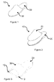
- FIG. 1 is a perspective view of an embodiment of the present invention
- FIG. 2 is a perspective view of the embodiment of FIG. 1 , with the upper member detached from the sole member;
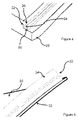
- FIG. 3 is a perspective, cross-sectional view of the embodiment of FIG. 1 , showing an attachment mechanism
- FIG. 4 is a perspective view of the locking body of the attachment mechanism of FIG. 3 ;
- FIG. 5 is a perspective view of the rail body of the attachment mechanism of FIG. 3 ;
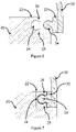
- FIG. 6 is a cross-sectional view of the attachment mechanism of FIG. 3 , wherein the rail member and the locking member are detached;
- FIG. 7 is a cross-sectional view of the attachment mechanism of FIG. 3 , wherein the rail member and the locking member are engaged;
- FIG. 8 is a perspective view of the embodiment of FIG. 1 , describing the placement of the upper member on the sole member;
- FIG. 9 is a top view of the embodiment of FIG. 1 , describing the attachment of the upper member to the sole member.
- a shoe 10 of the present invention comprises a sole member 20 , a detachable, replaceable upper member 30 , and an attachment mechanism 12 for attaching the upper member 30 securely to the sole member 20 .
- An embodiment of a shoe 10 according to the present invention is shown in FIGS. 1 , 2 , 8 , and 9 .
- Such a configuration may enable the wearer to, for example, wear a pair of shoes whose left and right uppers are of two different colors, corresponding to, for example, the two colors of a favorite sports team.
- An embodiment is an example or implementation of the inventions.
- the various appearances of “one embodiment,” “an embodiment” or “some embodiments” do not necessarily all refer to the same embodiments.
- Methods of the present invention may be implemented by performing or completing manually, automatically, or a combination thereof selected steps or tasks.
- method refers to manners, means, techniques and procedures for accomplishing a given task including, but is not limited to those manners, means, techniques and procedures either known to, or readily developed from known manners, means, techniques and procedures by practitioners of the art to which the invention belongs.
- bottom”, “below”, “top” and “above” as used herein do not necessarily indicate that a “bottom” component is below a “top” component, or that a component that is “below” is indeed “below” another component or that a component that is “above” is indeed “above” another component.
- directions, components or both may be flipped, rotated, moved in space, placed in a diagonal orientation or position, placed horizontally or vertically, or similarly modified.
- the terms “bottom”, “below”, “top” and “above” may be used herein for exemplary purposes only, to illustrate the relative positioning or placement of certain components, to indicate a first and a second component or to do both.
- sole member 20 may be any type of footwear sole as is known in the art, including, inter alia, athletic soles and soles with various height heels. Accordingly, sole member 20 may be constructed from any suitable material and may include one or more layers of material. Additionally, sole member 20 may have at least one area of padding. According to embodiments, sole member 20 extends from the toe area to the heel area of the foot.
- upper member 30 of shoe 10 is both detachable from sole member 20 and replaceable.
- a user is able to, for example, purchase a plurality of upper members 30 of different styles and colors that may be used with a single pair of sole members 20 .
- the wearer may also have the option, for example, of attaching a single upper member 30 to a plurality of sole members 20 that have, for example different height heels.
- upper member 30 may be constructed from any suitable, flexible material. Upper member 30 may, furthermore, be designed in any of the many styles and colors suitable to the upper portion of footwear.
- Upper member 30 covers at least a portion of the forward part of the foot. According to some embodiments, upper member 30 may also cover the lateral sides of the foot or the heel area of the foot or both. According to some other embodiments, shoe 10 may have two or more detachable upper members 30 , for example, a front strap and a heel support strap.
- the attachment mechanism 12 used to affix upper member 30 to sole member 20 comprises a locking body 22 and a corresponding rail body 32 .
- Locking body 22 creates a perimeter along at least a portion of sole member 20 . According to some embodiments, locking body 22 resides on the upper edge of sole member 20 as seen in FIG. 3 .
- Locking body 22 may be attached to sole member 20 using any suitable method.
- locking body 22 may be manufactured as an extrusion that integrally extends from sole member 20 , or glue may be used to bond locking body 22 to sole member 20 .
- Locking body 22 may be constructed from sturdy, flexible material such as, for example, plastic, rubber, or silicon.
- Channel 24 there is an elongated coupling channel 24 , seen in FIG. 4 , that extends along the length of locking body 22 .
- Channel 24 may be defined by an upper arm 26 and a lower arm 28 .
- Upper arm 26 and lower arm 28 have flanged ends and further function to grasp rail body 32 when locking body 22 and rail body 32 are engaged.
- Rail body 32 seen in FIGS. 5 , 6 , and 7 , is affixed to at least a portion of the edge of upper member 30 that will engage sole member 20 . According to embodiments, rail body 32 may be positioned along part or all of the edge of upper member 30 .
- Rail body 32 may be attached to upper member 30 using any suitable method.
- rail body 32 may be manufactured as an extrusion that integrally extends from upper member 30 , or glue may be used to bond rail body 32 to upper member 30 .
- Rail body 32 may be constructed from sturdy, flexible material such as, for example, plastic, rubber, or silicon.
- Rail body 32 has a protruding rail head 34 that engages channel 24 of locking body 22 .
- rail head 34 may be substantially spherical in shape.
- rail head 34 may be of another shape such as, for example, triangular or elliptical.
- upper arm 26 and lower arm 28 of locking body 22 securely hold rail head 34 in place.
- FIG. 6 shows a cross-sectional view of an attachment mechanism 12 , wherein rail body 32 and locking body 22 have not yet been engaged.
- FIG. 9 describes the step of engaging rail body 32 of upper member 30 to locking body 22 of sole member 20 .
- Pressure is applied to rail body 32 , as indicated by arrowed lines B, which moves upper member 30 in the direction indicated by the arrowed lines C.
- rail head 34 of rail body 32 is inserted into channel 24 of locking body 22 , the flanged ends of upper arm 26 and lower arm 28 grasp rail head 34 , securely engaging rail head 34 within channel 24 .
- FIG. 7 shows a cross-sectional view of attachment mechanism 12 , wherein rail head 34 is seated in channel 24 and grasped by upper arm 26 and lower arm 28 thus securely engaging rail body 32 to locking body 22 .
- locking body 22 may be affixed to upper member 30 and corresponding rail body 32 may be affixed to sole member.
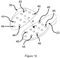
- FIG. 10 An alternative method of attaching upper member 30 to sole member 20 is described in FIG. 10 .
- a membrane 42 may be affixed to the lower edges of upper member 30 , thereby substantially enclosing upper member 30 .
- An array of boss parts 44 may be disposed over the outer surface of membrane 42 .
- boss parts 44 and gib cavities 46 are shaped such that the engagement of boss parts 44 into the corresponding gib cavities 46 enables detachably faying upper member 30 to sole member 20 .
- the engagement of boss parts 44 into the gib cavities 46 may occur when the wearer inserts his foot into upper member 30 and then steps on sole member 20 . The weight of the wearer will be sufficient to set boss parts 44 into gib cavities 46 .
- an array of short locking bodies 22 and corresponding rail bodies 32 may be positioned along the edges for upper member 30 and sole member 20 , rather than a single elongated locking body 22 and a single corresponding rail body 32 .
- magnets may be added to rail body 32 or locking body 22 or both in order to reinforce the connection of upper member 30 to sole member 20 .
Abstract
The present invention provides a shoe having a sole member, a detachable, replaceable upper member, and a fastening mechanism for coupling the upper member to the sole member, wherein the fastening mechanism comprises an interlocking rail body and locking body.
Description
- This invention relates generally to footwear, and more specifically to an attachment mechanism for footwear with detachable, replaceable uppers.
- Shoes that have replaceable uppers are known. Such an arrangement may comprise, for example, a shoe whose sole may accommodate a plurality of detachable uppers of differing styles, colors, and shapes. These shoes may offer many advantages. For example, the replaceable upper portion of the shoes may be purchased at a lower cost than an entire pair of shoes, encouraging the purchase of new shoes. A plurality of replaceable uppers may also require less storage space than multiple pairs of shoes, an advantage not only to the consumer but also to manufacturers and retailers.
- Attempts such as those listed herein have been made to provide attachments mechanisms for shoes with replaceable uppers. U.S. Pat. No. 4,839,948, which requires a plurality of receptacles within a recess in the sole of a shoe for receiving lugs, is not applicable to extruded, thin, or flexible soles. U.S. Pat. No. 4,745,693, which teaches of an athletic shoe whose upper portion is releasably joined to the sole-and-heel portion by a circumferential zipper connection means, is not practical for other shoe styles such as, for example, an open-toe dress shoe. US2004128859, which presents a detachable strap connection to a shoe bottom, is applicable only to shoes with rigid soles. US2006112597, which provides an attachment mechanism and system with interchangeable uppers or straps, is not practical for closed-toe shoes. U.S. Pat. No. 2,519,108, which discloses a shoe with a detachable upper portion, also requires that the shoe have a heel strap.
- However, these inventions, for reasons that will become apparent, simply do not provide versatile, easy-to-use, and cost effective attachment mechanism s that are applicable to a plurality of sole and upper types in accordance with the principle of the present invention.
- The main objective of the present invention is to provide an attachment mechanism for footwear that has detachable, replaceable uppers, that is simple to operate, cost effective to manufacture, and may be used with a plurality of shoe styles and types. A key feature of the present invention is the interlocking rail member and locking member that comprise the attachment mechanism.
- Accordingly, in order to accomplish the above objective, the present invention provides a shoe having a sole member, a detachable, replaceable upper member, and a fastening mechanism for coupling the upper member to the sole member, wherein the fastening mechanism comprises an interlocking rail body and locking body.
- These and other objectives, features, and advantages of the present invention will become apparent from the following detailed description, the accompanying drawings, and the appended claims.
- The subject matter regarded as the invention will become more clearly understood in light of the ensuing description of embodiments herein, given by way of example and for purposes of illustrative discussion of the present invention only, with reference to the accompanying drawings, wherein
-
FIG. 1 is a perspective view of an embodiment of the present invention; -
FIG. 2 is a perspective view of the embodiment ofFIG. 1 , with the upper member detached from the sole member; -
FIG. 3 is a perspective, cross-sectional view of the embodiment ofFIG. 1 , showing an attachment mechanism; -
FIG. 4 is a perspective view of the locking body of the attachment mechanism ofFIG. 3 ; -
FIG. 5 is a perspective view of the rail body of the attachment mechanism ofFIG. 3 ; -
FIG. 6 is a cross-sectional view of the attachment mechanism ofFIG. 3 , wherein the rail member and the locking member are detached; -
FIG. 7 is a cross-sectional view of the attachment mechanism ofFIG. 3 , wherein the rail member and the locking member are engaged; and -
FIG. 8 is a perspective view of the embodiment ofFIG. 1 , describing the placement of the upper member on the sole member; -
FIG. 9 is a top view of the embodiment ofFIG. 1 , describing the attachment of the upper member to the sole member. - The drawings together with the description make apparent to those skilled in the art how the invention may be embodied in practice.
- No attempt is made to show structural details of the invention in more detail than is necessary for a fundamental understanding of the invention.
- It will be appreciated that for simplicity and clarity of illustration, elements shown in the figures have not necessarily been drawn to scale. For example, the dimensions of some of the elements may be exaggerated relative to other elements for clarity. Further, where considered appropriate, reference numerals may be repeated among the figures to indicate corresponding or analogous elements.
- Referring now in detail to the drawings, a
shoe 10 of the present invention comprises asole member 20, a detachable, replaceableupper member 30, and anattachment mechanism 12 for attaching theupper member 30 securely to thesole member 20. An embodiment of ashoe 10 according to the present invention is shown inFIGS. 1 , 2, 8, and 9. - Such a configuration may enable the wearer to, for example, wear a pair of shoes whose left and right uppers are of two different colors, corresponding to, for example, the two colors of a favorite sports team.
- An embodiment is an example or implementation of the inventions. The various appearances of “one embodiment,” “an embodiment” or “some embodiments” do not necessarily all refer to the same embodiments.
- Although various features of the invention may be described in the context of a single embodiment, the features may also be provided separately or in any suitable combination. Conversely, although the invention may be described herein in the context of separate embodiments for clarity, the invention may also be implemented in a single embodiment.
- Reference in the specification to “one embodiment”, “an embodiment”, “some embodiments” or “other embodiments” means that a particular feature, structure, or characteristic described in connection with the embodiments is included in at least one embodiment, but not necessarily all embodiments, of the inventions.
- It is understood that the phraseology and terminology employed herein is not to be construed as limiting and is for descriptive purpose only.
- The principles and uses of the teachings of the present invention may be better understood with reference to the accompanying description, figures and examples.
- It is to be understood that the details set forth herein do not construe a limitation to an application of the invention. Furthermore, it is to be understood that the invention can be carried out or practiced in various ways and that the invention can be implemented in embodiments other than the ones outlined in the description below.
- It is to be understood that the terms “including”, “comprising”, “consisting” and grammatical variants thereof do not preclude the addition of one or more components, features, steps, integers or groups thereof and that the terms are not to be construed as specifying components, features, steps or integers.
- The phrase “consisting essentially of”, and grammatical variants thereof, when used herein is not to be construed as excluding additional components, steps, features, integers or groups thereof but rather that the additional features, integers, steps, components or groups thereof do not materially alter the basic and novel characteristics of the claimed composition, device or method.
- If the specification or claims refer to “an additional” element, that does not preclude there being more than one of the additional element.
- It is to be understood that where the claims or specification refer to “a” or “an” element, such reference is not to be construed as there being only one of that element.
- It is to be understood that where the specification states that a component, feature, structure, or characteristic “may”, “might”, “can” or “could” be included, that particular component, feature, structure, or characteristic is not required to be included.
- Where applicable, although state diagrams, flow diagrams or both may be used to describe embodiments, the invention is not limited to those diagrams or to the corresponding descriptions. For example, flow need not move through each illustrated box or state, or in exactly the same order as illustrated and described.
- Methods of the present invention may be implemented by performing or completing manually, automatically, or a combination thereof selected steps or tasks.
- The term “method” refers to manners, means, techniques and procedures for accomplishing a given task including, but is not limited to those manners, means, techniques and procedures either known to, or readily developed from known manners, means, techniques and procedures by practitioners of the art to which the invention belongs.
- The descriptions, examples, methods and materials presented in the claims and the specification are not to be construed as limiting but rather as illustrative only.
- Meanings of technical and scientific terms used herein are to be commonly understood as by one of ordinary skill in the art to which the invention belongs, unless otherwise defined.
- The present invention can be implemented in the testing or practice with methods and materials equivalent or similar to those described herein.
- The terms “bottom”, “below”, “top” and “above” as used herein do not necessarily indicate that a “bottom” component is below a “top” component, or that a component that is “below” is indeed “below” another component or that a component that is “above” is indeed “above” another component. As such, directions, components or both may be flipped, rotated, moved in space, placed in a diagonal orientation or position, placed horizontally or vertically, or similarly modified. Accordingly, it will be appreciated that the terms “bottom”, “below”, “top” and “above” may be used herein for exemplary purposes only, to illustrate the relative positioning or placement of certain components, to indicate a first and a second component or to do both.
- Any publications, including patents, patent applications and articles, referenced or mentioned in this specification are herein incorporated in their entirety into the specification, to the same extent as if each individual publication was specifically and individually indicated to be incorporated herein. In addition, citation or identification of any reference in the description of some embodiments of the invention shall not be construed as an admission that such reference is available as prior art to the present invention.
- According to embodiments,
sole member 20 may be any type of footwear sole as is known in the art, including, inter alia, athletic soles and soles with various height heels. Accordingly,sole member 20 may be constructed from any suitable material and may include one or more layers of material. Additionally,sole member 20 may have at least one area of padding. According to embodiments,sole member 20 extends from the toe area to the heel area of the foot. - According to embodiments,
upper member 30 ofshoe 10 is both detachable fromsole member 20 and replaceable. Thus, a user is able to, for example, purchase a plurality ofupper members 30 of different styles and colors that may be used with a single pair ofsole members 20. The wearer may also have the option, for example, of attaching a singleupper member 30 to a plurality ofsole members 20 that have, for example different height heels. - According to embodiments,
upper member 30 may be constructed from any suitable, flexible material.Upper member 30 may, furthermore, be designed in any of the many styles and colors suitable to the upper portion of footwear. -
Upper member 30 covers at least a portion of the forward part of the foot. According to some embodiments,upper member 30 may also cover the lateral sides of the foot or the heel area of the foot or both. According to some other embodiments,shoe 10 may have two or more detachableupper members 30, for example, a front strap and a heel support strap. - According to embodiments, the
attachment mechanism 12 used to affixupper member 30 tosole member 20 comprises a lockingbody 22 and acorresponding rail body 32. - Locking
body 22, seen inFIGS. 4 , 6, and 7, creates a perimeter along at least a portion ofsole member 20. According to some embodiments, lockingbody 22 resides on the upper edge ofsole member 20 as seen inFIG. 3 . - Locking
body 22 may be attached tosole member 20 using any suitable method. For example, lockingbody 22 may be manufactured as an extrusion that integrally extends fromsole member 20, or glue may be used to bond lockingbody 22 tosole member 20. Lockingbody 22 may be constructed from sturdy, flexible material such as, for example, plastic, rubber, or silicon. - According to embodiments, there is an
elongated coupling channel 24, seen inFIG. 4 , that extends along the length of lockingbody 22.Channel 24 may be defined by anupper arm 26 and alower arm 28.Upper arm 26 andlower arm 28 have flanged ends and further function to grasprail body 32 when lockingbody 22 andrail body 32 are engaged. -
Rail body 32, seen inFIGS. 5 , 6, and 7, is affixed to at least a portion of the edge ofupper member 30 that will engagesole member 20. According to embodiments,rail body 32 may be positioned along part or all of the edge ofupper member 30. -
Rail body 32 may be attached toupper member 30 using any suitable method. For example,rail body 32 may be manufactured as an extrusion that integrally extends fromupper member 30, or glue may be used tobond rail body 32 toupper member 30.Rail body 32 may be constructed from sturdy, flexible material such as, for example, plastic, rubber, or silicon. -
Rail body 32 has a protrudingrail head 34 that engageschannel 24 of lockingbody 22. According to some embodiments,rail head 34 may be substantially spherical in shape. According to other embodiments,rail head 34 may be of another shape such as, for example, triangular or elliptical. - When
rail head 34 is inserted intochannel 24,upper arm 26 andlower arm 28 of lockingbody 22 securely holdrail head 34 in place. - In order to more fully describe the present invention, the following describes a mode of use, with reference made to
FIGS. 6 , 7, 8, and 9. - The wearer may select an
upper member 30 for attachment tosole member 20, and as shown inFIG. 8 ,upper member 30 may be placed oversole member 20, in the direction of arrowed line A.FIG. 6 shows a cross-sectional view of anattachment mechanism 12, whereinrail body 32 and lockingbody 22 have not yet been engaged. -
FIG. 9 describes the step of engagingrail body 32 ofupper member 30 to lockingbody 22 ofsole member 20. Pressure is applied to railbody 32, as indicated by arrowed lines B, which movesupper member 30 in the direction indicated by the arrowed lines C. Whenrail head 34 ofrail body 32 is inserted intochannel 24 of lockingbody 22, the flanged ends ofupper arm 26 andlower arm 28grasp rail head 34, securely engagingrail head 34 withinchannel 24. -
FIG. 7 shows a cross-sectional view ofattachment mechanism 12, whereinrail head 34 is seated inchannel 24 and grasped byupper arm 26 andlower arm 28 thus securely engagingrail body 32 to lockingbody 22. According to some alternative embodiments, lockingbody 22 may be affixed toupper member 30 and correspondingrail body 32 may be affixed to sole member. - An alternative method of attaching
upper member 30 tosole member 20 is described inFIG. 10 . According to such an embodiment, amembrane 42 may be affixed to the lower edges ofupper member 30, thereby substantially enclosingupper member 30. An array ofboss parts 44 may be disposed over the outer surface ofmembrane 42. Across the upper surface ofsole member 20 there may be disposed a corresponding array ofgib cavities 46. According to embodiments,boss parts 44 andgib cavities 46 are shaped such that the engagement ofboss parts 44 into the correspondinggib cavities 46 enables detachably fayingupper member 30 tosole member 20. The engagement ofboss parts 44 into thegib cavities 46 may occur when the wearer inserts his foot intoupper member 30 and then steps onsole member 20. The weight of the wearer will be sufficient to setboss parts 44 intogib cavities 46. - According to some embodiments of the present invention, an array of
short locking bodies 22 and correspondingrail bodies 32 may be positioned along the edges forupper member 30 andsole member 20, rather than a singleelongated locking body 22 and a singlecorresponding rail body 32. - According to some embodiments, magnets may be added to
rail body 32 or lockingbody 22 or both in order to reinforce the connection ofupper member 30 tosole member 20. - While the invention has been described with respect to a limited number of embodiments, these should not be construed as limitations on the scope of the invention, but rather as exemplifications of some of the embodiments. Those skilled in the art will envision other possible variations, modifications, and applications that are also within the scope of the invention. Accordingly, the scope of the invention should not be limited by what has thus far been described, but by the appended claims and their legal equivalents. Therefore, it is to be understood that alternatives, modifications, and variations of the present invention are to be construed as being within the scope and spirit of the appended claims.
Claims (13)
1. A shoe having a sole member, a detachable, replaceable upper member, and a fastening mechanism for coupling the upper member to the sole member,
wherein the fastening mechanism comprises an interlocking rail body and a corresponding locking body.
2. A shoe of claim 1 , wherein a single, elongate rail body is affixed to at least one portion of the edge of the upper member and a single, elongate locking body is affixed to a corresponding portion of the sole member.
3. A shoe of claim 1 , wherein the rail body has a rail head protruding therefrom that couples with an elongate channel in the locking body.
4. A shoe of claim 3 , wherein the rail head has a substantially spherical shape.
5. A shoe of claim 3 , wherein the channel of the locking body accommodates the shape of the rail head.
6. A shoe of claim 3 , wherein the locking body has an upper arm and a lower arm with flanged ends for grasping the rail head when the rail body is coupled to the locking body.
7. A shoe of claim 1 , wherein the fastening mechanism is reinforced with a magnet.
8. A shoe of claim 1 , wherein the upper member covers at least a portion of the forward part of the foot.
9. A shoe of claim 8 , wherein the upper member further covers at least one of a lateral side of the foot and the heel area of the foot.
10. A shoe of claim 1 , wherein the upper member is comprised of at least two pieces.
11. A shoe of claim 1 , wherein the locking body is affixed to the upper member and the corresponding rail body is affixed to the sole member.
12. A shoe of claim 1 , wherein an array of short locking bodies and corresponding rail bodies are positioned along the edges of the upper member and the sole member.
13. A shoe having a sole member, a detachable, replaceable upper member, a membrane affixed to the lower edges of said upper member, and a fastening mechanism for coupling the upper member to the sole member, wherein
the fastening mechanism comprises an array of boss parts disposed across the outer surface of the membrane, and a corresponding array of gib cavities disposed across the upper surface of the sole member, and
the engagement of the boss parts into the corresponding gib cavities enables detachably faying the upper member to the sole member.
Priority Applications (2)
| Application Number | Priority Date | Filing Date | Title |
|---|---|---|---|
| US11/552,588 US20080098623A1 (en) | 2006-10-25 | 2006-10-25 | Shoes with replaceable uppers |
| PCT/IL2007/001302 WO2008050346A2 (en) | 2006-10-25 | 2007-10-25 | Shoes with replaceable uppers |
Applications Claiming Priority (1)
| Application Number | Priority Date | Filing Date | Title |
|---|---|---|---|
| US11/552,588 US20080098623A1 (en) | 2006-10-25 | 2006-10-25 | Shoes with replaceable uppers |
Publications (1)
| Publication Number | Publication Date |
|---|---|
| US20080098623A1 true US20080098623A1 (en) | 2008-05-01 |
Family
ID=39325007
Family Applications (1)
| Application Number | Title | Priority Date | Filing Date |
|---|---|---|---|
| US11/552,588 Abandoned US20080098623A1 (en) | 2006-10-25 | 2006-10-25 | Shoes with replaceable uppers |
Country Status (2)
| Country | Link |
|---|---|
| US (1) | US20080098623A1 (en) |
| WO (1) | WO2008050346A2 (en) |
Cited By (27)
| Publication number | Priority date | Publication date | Assignee | Title |
|---|---|---|---|---|
| US20080235993A1 (en) * | 2007-03-16 | 2008-10-02 | Elizabeth Wegner | Shoe and interchangeable shoe cover systems |
| US20100037486A1 (en) * | 2008-08-12 | 2010-02-18 | Luisa Verheijen | Modular Shoe Apparatus |
| US7698834B1 (en) | 2006-11-09 | 2010-04-20 | Carolyn Courville | Shoe with interchangeable vamp and base |
| US20110088284A1 (en) * | 2009-05-22 | 2011-04-21 | Jonathan George Wruck | Detachable Shoe Cover For Open Toe Shoe Or Boot |
| US20120030866A1 (en) * | 2010-08-05 | 2012-02-09 | Jennifer Snider-Tornetta | Pedicure protector for use before, during and/or after a pedicure and method of using same |
| US20120227289A1 (en) * | 2011-03-08 | 2012-09-13 | Omni Trax Technology, Inc. | Interchangeable sole system |
| US20120260530A1 (en) * | 2011-04-18 | 2012-10-18 | Martha Jo Policastro | Convertible shoe with interchangeable vamp |
| US20130139408A1 (en) * | 2011-12-06 | 2013-06-06 | Albert Chaiken | Shoe with multiple selectable vamps |
| US20130219751A1 (en) * | 2012-02-23 | 2013-08-29 | Kimberly Ann Catlett | Shoe system with interchangeable uppers |
| GB2503033A (en) * | 2012-06-15 | 2013-12-18 | C & C Lifestyle Ltd | Shoe with detachable upper |
| US20150040434A1 (en) * | 2013-08-08 | 2015-02-12 | Cat Perkins LLC | Shoe with magnetic attachment mechanism |
| US20150351486A1 (en) * | 2014-01-13 | 2015-12-10 | Caroline A Opiyo | Shoe with a Replaceable Upper |
| US9468254B2 (en) | 2011-12-06 | 2016-10-18 | Albert Chaiken | Compact shoe wardrobe system implementing interchangeable vamps and bases |
| US9516912B2 (en) | 2013-04-25 | 2016-12-13 | ShaTona M. Mathis | Shoe with removable magnetic toe cap |
| CN106572719A (en) * | 2014-08-11 | 2017-04-19 | 钱德妮·塞西 | Adaptable shoe |
| US9737109B2 (en) * | 2015-05-07 | 2017-08-22 | Nike, Inc. | Footwear with removable midsole and outsole |
| US20170238647A1 (en) * | 2016-02-22 | 2017-08-24 | Christian Sharifi | Changeable Shoe Cover |
| US20170318895A1 (en) * | 2014-07-03 | 2017-11-09 | Gaynor Marie THOMASSON | A modular shoe |
| WO2018160760A1 (en) * | 2017-02-28 | 2018-09-07 | Redd Oaks | Shoe |
| US20180317608A1 (en) * | 2017-05-08 | 2018-11-08 | Nike, Inc. | Modular article of footwear and method of manufacturing customized article of footwear |
| US20190142105A1 (en) * | 2017-11-15 | 2019-05-16 | Kadima Forward Inc. | Adjustable footwear having interchangeable panels |
| US20190216172A1 (en) * | 2018-01-15 | 2019-07-18 | Stella McCartney Limited | Footwear sole and method of manufacture and related aspects |
| US20200015541A1 (en) * | 2018-07-13 | 2020-01-16 | Lamar Higginbotham | Customizable sandal system and method of use |
| US20210219662A1 (en) * | 2016-02-05 | 2021-07-22 | Precedo Capital, Llc | Footwear With One or More Removable and Interchangeable Panels |
| USD944498S1 (en) * | 2020-12-03 | 2022-03-01 | Joshua Tyson | Zip off footwear |
| US11350698B2 (en) * | 2020-03-03 | 2022-06-07 | Cindy Fogarty | Interchangeable shoe |
| DE102021111567A1 (en) | 2021-05-04 | 2022-11-10 | Nicolas Lederer | Modular system for sandals or shoes |
Families Citing this family (2)
| Publication number | Priority date | Publication date | Assignee | Title |
|---|---|---|---|---|
| GB201019651D0 (en) * | 2010-11-19 | 2010-12-29 | Bonelli Mauro | Fasteners for interconnecting footwear components, and footwear constructed using such fasteners |
| WO2016178063A1 (en) * | 2015-05-07 | 2016-11-10 | Mizrahi-Shapiro Eduardo Nuri | Footwear assembly |
Citations (18)
| Publication number | Priority date | Publication date | Assignee | Title |
|---|---|---|---|---|
| US2368314A (en) * | 1942-05-28 | 1945-01-30 | Marx Herman | Shoe structure |
| US2519108A (en) * | 1948-08-02 | 1950-08-15 | Fred V Bryant | Shoe having detachable upper |
| US2552943A (en) * | 1948-03-04 | 1951-05-15 | Jones & Malyon Ltd | Shoe having a detachable upper |
| US2761224A (en) * | 1952-08-04 | 1956-09-04 | Howard W Gardiner | Shoe with hollow welt for detachable upper |
| US3204346A (en) * | 1964-09-10 | 1965-09-07 | Ramona D Lockard | Interchangeable sole and upper for shoes |
| US3538628A (en) * | 1968-09-23 | 1970-11-10 | Lord Geller Federico & Partner | Footwear |
| US4267650A (en) * | 1979-07-30 | 1981-05-19 | Peter Bauer | Shoe with removable outsole |
| US4317294A (en) * | 1980-05-20 | 1982-03-02 | Goodyear Mark V | Replaceable shoe sole |
| US4377042A (en) * | 1979-07-30 | 1983-03-22 | Peter Bauer | Footwear having removable sole |
| US4745693A (en) * | 1987-02-09 | 1988-05-24 | Brown Randy N | Shoe with detachable sole and heel |
| US4839948A (en) * | 1986-05-23 | 1989-06-20 | Boros Leslie A | Convertible footwear |
| US4887369A (en) * | 1988-08-12 | 1989-12-19 | Angileen Bailey | Changeable shoe tops/heels |
| US5065531A (en) * | 1990-08-20 | 1991-11-19 | Prestridge Patrick L | Attachment device for providing detachable uppers in footwear and the like |
| US5317822A (en) * | 1992-10-19 | 1994-06-07 | Johnson Joshua F | Athletic shoe with interchangeable wear sole |
| US5970630A (en) * | 1994-01-07 | 1999-10-26 | Gallegos Alvaro Z | Rigid midsole footware structure with removable undercarriage attaching means |
| US20040128859A1 (en) * | 2001-02-08 | 2004-07-08 | Cambronero Enrique Martinez | Detachable straps connection to a shoe bottom |
| US20060112596A1 (en) * | 2004-12-01 | 2006-06-01 | Hillary Chan | Clasp for detachably securing footwear upper |
| US20060112597A1 (en) * | 2004-12-01 | 2006-06-01 | Tracy Stern | Locking mechanism for securing detachable shoe uppers |
-
2006
- 2006-10-25 US US11/552,588 patent/US20080098623A1/en not_active Abandoned
-
2007
- 2007-10-25 WO PCT/IL2007/001302 patent/WO2008050346A2/en active Application Filing
Patent Citations (18)
| Publication number | Priority date | Publication date | Assignee | Title |
|---|---|---|---|---|
| US2368314A (en) * | 1942-05-28 | 1945-01-30 | Marx Herman | Shoe structure |
| US2552943A (en) * | 1948-03-04 | 1951-05-15 | Jones & Malyon Ltd | Shoe having a detachable upper |
| US2519108A (en) * | 1948-08-02 | 1950-08-15 | Fred V Bryant | Shoe having detachable upper |
| US2761224A (en) * | 1952-08-04 | 1956-09-04 | Howard W Gardiner | Shoe with hollow welt for detachable upper |
| US3204346A (en) * | 1964-09-10 | 1965-09-07 | Ramona D Lockard | Interchangeable sole and upper for shoes |
| US3538628A (en) * | 1968-09-23 | 1970-11-10 | Lord Geller Federico & Partner | Footwear |
| US4377042A (en) * | 1979-07-30 | 1983-03-22 | Peter Bauer | Footwear having removable sole |
| US4267650A (en) * | 1979-07-30 | 1981-05-19 | Peter Bauer | Shoe with removable outsole |
| US4317294A (en) * | 1980-05-20 | 1982-03-02 | Goodyear Mark V | Replaceable shoe sole |
| US4839948A (en) * | 1986-05-23 | 1989-06-20 | Boros Leslie A | Convertible footwear |
| US4745693A (en) * | 1987-02-09 | 1988-05-24 | Brown Randy N | Shoe with detachable sole and heel |
| US4887369A (en) * | 1988-08-12 | 1989-12-19 | Angileen Bailey | Changeable shoe tops/heels |
| US5065531A (en) * | 1990-08-20 | 1991-11-19 | Prestridge Patrick L | Attachment device for providing detachable uppers in footwear and the like |
| US5317822A (en) * | 1992-10-19 | 1994-06-07 | Johnson Joshua F | Athletic shoe with interchangeable wear sole |
| US5970630A (en) * | 1994-01-07 | 1999-10-26 | Gallegos Alvaro Z | Rigid midsole footware structure with removable undercarriage attaching means |
| US20040128859A1 (en) * | 2001-02-08 | 2004-07-08 | Cambronero Enrique Martinez | Detachable straps connection to a shoe bottom |
| US20060112596A1 (en) * | 2004-12-01 | 2006-06-01 | Hillary Chan | Clasp for detachably securing footwear upper |
| US20060112597A1 (en) * | 2004-12-01 | 2006-06-01 | Tracy Stern | Locking mechanism for securing detachable shoe uppers |
Cited By (41)
| Publication number | Priority date | Publication date | Assignee | Title |
|---|---|---|---|---|
| US7698834B1 (en) | 2006-11-09 | 2010-04-20 | Carolyn Courville | Shoe with interchangeable vamp and base |
| US20080235993A1 (en) * | 2007-03-16 | 2008-10-02 | Elizabeth Wegner | Shoe and interchangeable shoe cover systems |
| US8316563B2 (en) * | 2007-03-16 | 2012-11-27 | Elizabeth Erika Wegner | Shoe and interchangeable shoe cover systems |
| US20100037486A1 (en) * | 2008-08-12 | 2010-02-18 | Luisa Verheijen | Modular Shoe Apparatus |
| US20110088284A1 (en) * | 2009-05-22 | 2011-04-21 | Jonathan George Wruck | Detachable Shoe Cover For Open Toe Shoe Or Boot |
| US20120030866A1 (en) * | 2010-08-05 | 2012-02-09 | Jennifer Snider-Tornetta | Pedicure protector for use before, during and/or after a pedicure and method of using same |
| US9451807B2 (en) * | 2010-08-05 | 2016-09-27 | Jennifer Snider-Tornetta | Pedicure protector for use before, during and/or after a pedicure and method of using same |
| US20120227289A1 (en) * | 2011-03-08 | 2012-09-13 | Omni Trax Technology, Inc. | Interchangeable sole system |
| US10681955B2 (en) * | 2011-03-08 | 2020-06-16 | Ot Intellectual Property, Llc | Interchangeable sole system |
| US20120260530A1 (en) * | 2011-04-18 | 2012-10-18 | Martha Jo Policastro | Convertible shoe with interchangeable vamp |
| US20130139408A1 (en) * | 2011-12-06 | 2013-06-06 | Albert Chaiken | Shoe with multiple selectable vamps |
| US9468254B2 (en) | 2011-12-06 | 2016-10-18 | Albert Chaiken | Compact shoe wardrobe system implementing interchangeable vamps and bases |
| US20130219751A1 (en) * | 2012-02-23 | 2013-08-29 | Kimberly Ann Catlett | Shoe system with interchangeable uppers |
| US10159301B2 (en) * | 2012-02-23 | 2018-12-25 | Kimberly Ann Catlett | Shoe system with interchangeable uppers |
| GB2503033A (en) * | 2012-06-15 | 2013-12-18 | C & C Lifestyle Ltd | Shoe with detachable upper |
| US9516912B2 (en) | 2013-04-25 | 2016-12-13 | ShaTona M. Mathis | Shoe with removable magnetic toe cap |
| US20150040434A1 (en) * | 2013-08-08 | 2015-02-12 | Cat Perkins LLC | Shoe with magnetic attachment mechanism |
| US10143261B2 (en) * | 2013-08-08 | 2018-12-04 | Cat Perkins Inc. | Shoe with magnetic attachment mechanism |
| US20180206587A1 (en) * | 2014-01-13 | 2018-07-26 | Caroline A. Opiyo | Shoe with a Replaceable Upper |
| US20150351486A1 (en) * | 2014-01-13 | 2015-12-10 | Caroline A Opiyo | Shoe with a Replaceable Upper |
| US20170318895A1 (en) * | 2014-07-03 | 2017-11-09 | Gaynor Marie THOMASSON | A modular shoe |
| US11234480B2 (en) * | 2014-07-03 | 2022-02-01 | Gaynor Marie THOMASSON | Modular shoe |
| US20170231316A1 (en) * | 2014-08-11 | 2017-08-17 | Chandni SETHI | Adaptable shoe |
| CN106572719A (en) * | 2014-08-11 | 2017-04-19 | 钱德妮·塞西 | Adaptable shoe |
| US9737109B2 (en) * | 2015-05-07 | 2017-08-22 | Nike, Inc. | Footwear with removable midsole and outsole |
| US11311072B2 (en) | 2015-05-07 | 2022-04-26 | Nike, Inc. | Footwear with removable midsole and outsole |
| US10531700B2 (en) | 2015-05-07 | 2020-01-14 | Nike, Inc. | Footwear with removable midsole and outsole |
| US20210219662A1 (en) * | 2016-02-05 | 2021-07-22 | Precedo Capital, Llc | Footwear With One or More Removable and Interchangeable Panels |
| US20170238647A1 (en) * | 2016-02-22 | 2017-08-24 | Christian Sharifi | Changeable Shoe Cover |
| WO2018160760A1 (en) * | 2017-02-28 | 2018-09-07 | Redd Oaks | Shoe |
| US20210235816A1 (en) * | 2017-05-08 | 2021-08-05 | Nike, Inc. | Modular article of footwear and method of manufacturing customized article of footwear |
| US11013296B2 (en) * | 2017-05-08 | 2021-05-25 | Nike, Inc. | Modular article of footwear and method of manufacturing customized article of footwear |
| US20180317608A1 (en) * | 2017-05-08 | 2018-11-08 | Nike, Inc. | Modular article of footwear and method of manufacturing customized article of footwear |
| US11723435B2 (en) * | 2017-05-08 | 2023-08-15 | Nike, Inc. | Modular article of footwear and method of manufacturing customized article of footwear |
| US20190142105A1 (en) * | 2017-11-15 | 2019-05-16 | Kadima Forward Inc. | Adjustable footwear having interchangeable panels |
| US20220039508A1 (en) * | 2017-11-15 | 2022-02-10 | Kadima Forward Inc. | Adjustable Footwear Having Interchangeable Panels |
| US20190216172A1 (en) * | 2018-01-15 | 2019-07-18 | Stella McCartney Limited | Footwear sole and method of manufacture and related aspects |
| US20200015541A1 (en) * | 2018-07-13 | 2020-01-16 | Lamar Higginbotham | Customizable sandal system and method of use |
| US11350698B2 (en) * | 2020-03-03 | 2022-06-07 | Cindy Fogarty | Interchangeable shoe |
| USD944498S1 (en) * | 2020-12-03 | 2022-03-01 | Joshua Tyson | Zip off footwear |
| DE102021111567A1 (en) | 2021-05-04 | 2022-11-10 | Nicolas Lederer | Modular system for sandals or shoes |
Also Published As
| Publication number | Publication date |
|---|---|
| WO2008050346A2 (en) | 2008-05-02 |
| WO2008050346A3 (en) | 2009-05-07 |
Similar Documents
| Publication | Publication Date | Title |
|---|---|---|
| US20080098623A1 (en) | Shoes with replaceable uppers | |
| US10413804B2 (en) | Skate with injected boot form | |
| US4103440A (en) | Shoe with detachable upper | |
| CN101478893B (en) | A shoe | |
| US5410821A (en) | Shoe with interchangable soles | |
| US8322054B2 (en) | Shoe with interchangeable strap system | |
| US6029376A (en) | Article of footwear | |
| US6754983B2 (en) | Article of footwear including a tented upper | |
| US7730636B2 (en) | Cleated article of footwear and method of manufacture | |
| US9167868B1 (en) | Shoe with embedded strap anchor | |
| US20100275462A1 (en) | Shoe | |
| CA2845354C (en) | Hockey skate | |
| US8250779B2 (en) | Overshoe | |
| US20130125415A1 (en) | Anti-fatigue ply rib construction | |
| JP2011212461A (en) | Cleat protector shoe cover | |
| US20200268103A1 (en) | Modular shoe system | |
| US20080052957A1 (en) | Disposable shoe cover for athletic use | |
| US9656153B2 (en) | Skate boot with monocoque body | |
| US9232828B2 (en) | Article of footwear with customizable stiffness | |
| US20140013621A1 (en) | Convertible Footwear | |
| US9131751B1 (en) | Shoe having elastic tongue-securing straps | |
| EP3624626B1 (en) | Shoe | |
| US20050034332A1 (en) | Interchangeable shoe assembly | |
| US9044060B2 (en) | Convertible shoe | |
| US11213737B2 (en) | Figure skating boot with monocoque structure |
Legal Events
| Date | Code | Title | Description |
|---|---|---|---|
| STCB | Information on status: application discontinuation |
Free format text: ABANDONED -- FAILURE TO RESPOND TO AN OFFICE ACTION |